Sponge Physics
 
Panel Porosity

Most sponge panels are perforated for weight reduction and/or for propellant cross flow. The panel porosity will affect a sponge's performance. If there are too many holes or if the holes are too large, the sponge may not fill with propellant and/or may leak more propellant than calculated during accelerations.

Large holes may allow gas to be trapped within the sponge because liquid, when filling the sponge, travels around the hole as opposed to across the hole as desired.

Too many holes effectively increase the contact angle and thus reduce the surface tension forces able to oppose the hydrostatics. In fact any panel porosity will have some effect on performance. The porosity used in panel must be fully explored and understood to ensure proper sponge performance.

3D Surface Rising Between Sponge Porous Panels

   
Basics
 

Wetting liquids cling in the corners formed by solid PMD components. By placing sponge panels (thin solid sheets) in close proximity to one another, liquid will reside within the gaps and large amounts of propellant may be controlled even during thruster accelerations.

The sponge illustrated in the figure to the left is subjected to a lateral acceleration. The propellant remains within the sponge against the hydrostatics only if the upper radius is sufficiently smaller than the lower radius. In the most basic terms, the surface pressure differential will be balanced by the hydrostatics. If the surface tension pressure is insufficient to overcome the hydrostatics, the sponge will not retain propellant. The simple force balance can be expressed as:

Details

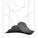
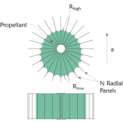
A set of equations can be derived for the surface location within the sponge and depends upon the sponge geometry. For example, the surface within a sponge with radial sponge panels (as illustrated above) is defined by:

a

Solving this equation for a specific sponge and across a variety of reference conditions reveals a couple of interesting phenomenon.

First, at a sufficiently high lateral acceleration, the propellant need not be continuous and can reside within two separate regions of the sponge. This could create isolated, inaccessible propellant within the sponge and occurs if

a


Second, the surface depends upon a reference surface location and radius of curvature (0 subscript). The initial position will be defined by the leak paths (or drip path) near the sponge. The final position will be dictated by the porous element pick up near or within the sponge.

The leak path is particularly important. If a PMD structure, such as a vane, is too close to the sponge, all of the sponge propellant may leak out via the vane - rendering the sponge useless. An example of this in one g can be demonstrated by considering a household sponge suspended in mid air vs. one sitting on a paper towel which extends over a counter. In the later case, the paper towel is a leak path and much of the water in the sponge will leak out leaving less liquid behind for use. Properly controlling the leak path is essential for maximum sponge performance.

For more information on the design, use, and physics of sponges please see

AIAA 93-1970 Propellant Management Device Conceptual Design and Analysis: Sponges